Some links in this article have expired and have been removed.
The past two weeks I have been working on terrain, and for two months or so before that I have (at irregular intervals) been researching and planning this work. Now finally the geometry-generation part of the terrain code is as good as completed.
The first thing I had to decide was what kind of technique to use. There are tons of ways to deal with terrain and a lot of papers/literature on it. I have some ideas on what the super secret project will need in terms of terrain, but still wanted to to keep it as open as possible so that the tech I made now would not become unusable later on. Because of this I needed to use something that felt customizable and scalable, and be able to fit the needs that might arise in the future.
Generating vertices
What I decided on was a an updated version of geomipmapping. My main resources was the original paper from 2000 (found here) and the terrain paper for the Frostbite Engine that power Battlefield: Bad Company (see presentation here). Basically, the approach works by having a heightmap of the terrain and then generate all geometry on the GPU. This limits the game to Shader Model 3 cards (for NVIDIA at least, ATI only has it in Shader model 4 cards in OpenGL) as the height map texture needs to be accessed in the vertex shader. This means fewer cards will be able to play the game, but since we will not release until 2 years or so from now that should not be much of a problem. Also, it would be possible to add a version that precomputes the geometry if it was really needed.
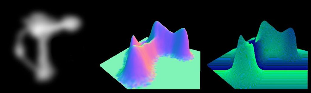
The good thing about doing geomipmapping on the GPUis that it is very easy to vary the amount of detail used and it saves a lot of memory (the heightmap takes about about a 1/10 of what the vertex data does). Before I go into the geomipmapping algorithm, I will first discuss how to generate the actual data. Basically, what you do is render one or several vertex grids that read from the heightmap and then offset the y-coordinate for each vertex. The normal is also generated by taking four height samples around current heightmap texel. Here is what it looks in in the G-buffer when normal and depth are generated from a heightmap (which is also included in the image):
Since I spent some time with figuring out normal generation algorithm, here is some explaination on that. The basic algorithm is as follows:
h0 = height(x+1, z);
h1 = height(x-1, z);
h2 = height(x, z+1);
h3 = height(x, z+1);
normal = normalize(h1-h0, 2 * height_texel_ratio, h3-h2);
What happens here is that the slope is calculated along the x-axis and then z-axis. Slope is defined by:
dx= (h1-h0) / (x1-x0)
or put in words, the difference in height divided by the difference in length. But since the distance is always 2 units for both the x and z, slope we can skip this division and simply just go with the difference in height. Now for the y-part, which we wants to be 1 when both slopes are 0 and then gradually lower as the other slopes get higher. For this algorithm we set it to 2 though since we want to get the rid of the division with 2 (which means multiplying all axes by 2). But a problem remains, and that is that actual height value is not always in the same units as the heightmap texels spacing. To fix this, we need to add a multiplier to the y-axis, which is calculated like this:
height_texel_ratio = max_height / unit_size
I save the heightmap in a normalized form, which means all values are between 1-0, and max_height is what each value is multiplied with when calculating the vertex y-value. The unitsize variable is what a texel represent in world space.
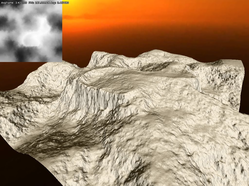
This algorithm is not that exact as it does not not take into account the diagonal slopes and such. It works pretty nice though and gives nice results. Here is how it looks when it is shaded:
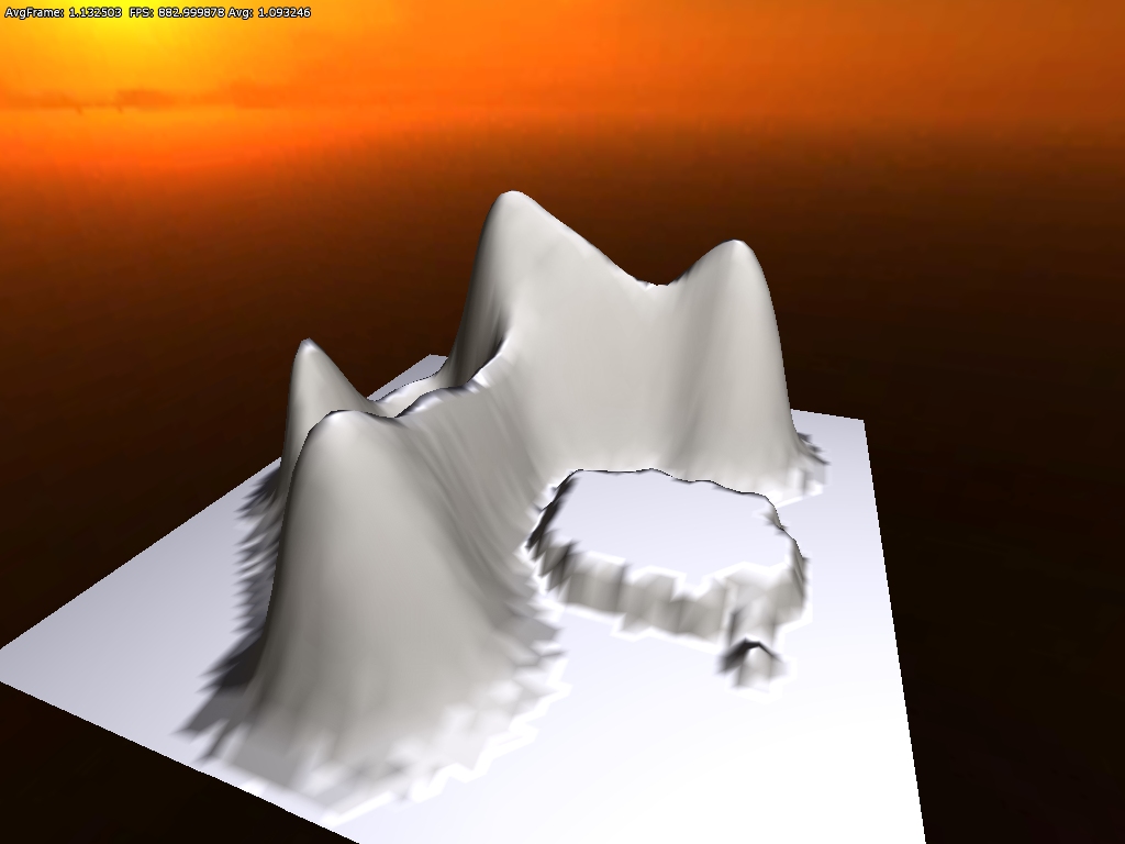
Note that here are some bumpy surfaces at the base the hills. The is because of precision issues in the heightmap I was using (only used 8bits in the first tests) and is something I will get back to.
Geomipmapping
The basic algorithm is pretty simple and is basically that the longer a part of the terrain is from the camera, the less vertices are used the render it. This works by having a single grid mesh, called patch, that is drawn many times, each time reperesenting a different part of the terrain. When a terrain patch is near the camera, there is a 1:1 vertex-to-texel coverage ratio, meaning that the grid covers a small part of the terrain in the highest possible resolution. Then as patches gets further away, the ratio gets smaller, and and grid covers a greater area but fewer vertices. So for really far away parts of the environment the ratio might be something like 1:128. The idea is that because the part is so far off the details are not visible anyway and each ratio can be a called a LOD-level.
The way this works internally is that a quadtree represent different the different LOD-levels. The engine then traverse this tree and if a node is found beyond a certain distance from the camera then it is picked. The lowest level nodes, with the smallest vertex-to-pixel ratio, are always picked if no other parent node meet the distance requirement. In this fashion the world is built up each frame.
The problem is now to determine what distance that a certain LOD-level is usable from and the original paper has some equations on how to do this. This is based on the change in the height of the details, but I skipped having such calculations and just let it be user set instead. This is how it looks in action:
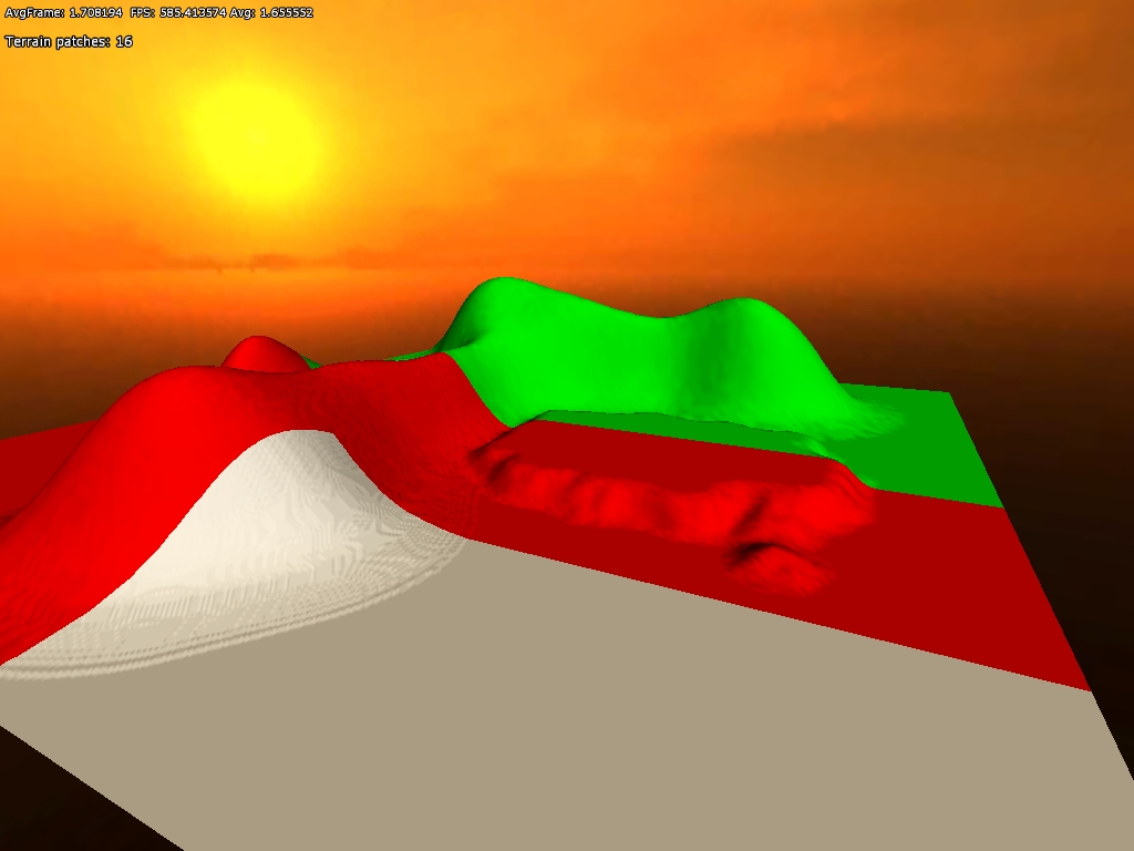
White (grey) areas represent a 1:1 ratio, red 1:2 and green 1:4. Now a problem emerges when using grids of different levels next to one another: You get t-junctions where the grids meet (because where the 1:1 patch has two grid quads, the 2:1 has only one) , resulting in visible seams. The fix this, there needs to be special grid pieces in the intersections that create a better transition. The pieces look like this (for a 4×4 grid patch):
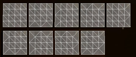
While there are 16 border permutations in total, only 9 are needed because of how the patches are generated from the quadtree. The same vertex buffer is used for all of these types of patches, and only the index buffer is changed, saving some storage and speeding up rendering a bit (no switch of vertex buffer needed).
The problem is now that there must be a maximum of 1 in level difference between patches. To make sure of this the distance checked, which I talked about earlier, needs to take this into account. This distance is calculated by taking the minimum distance from the previous level (0 for lowest ratio) and add the diagonal of the AABB (where height is max height) from the previous level.
Improving precision
As mentioned before, I used a 8bit texture for height for the early tests. This gives pretty lousy precision so I needed to generate one with higher bit depth. Also, older cards must use a 32bit float shader in the vertex shader, so having this was crucial in several ways. To get hold of this texture I used the demo version of GeoControl and generated a 32bit heightmap in a raw uncompressed format. Loading that into the code I already had gave me this pretty picture:
To test how the algorithm worked with larger draw distances, I scaled up the terrain to cover 1×1 km and added some fog:
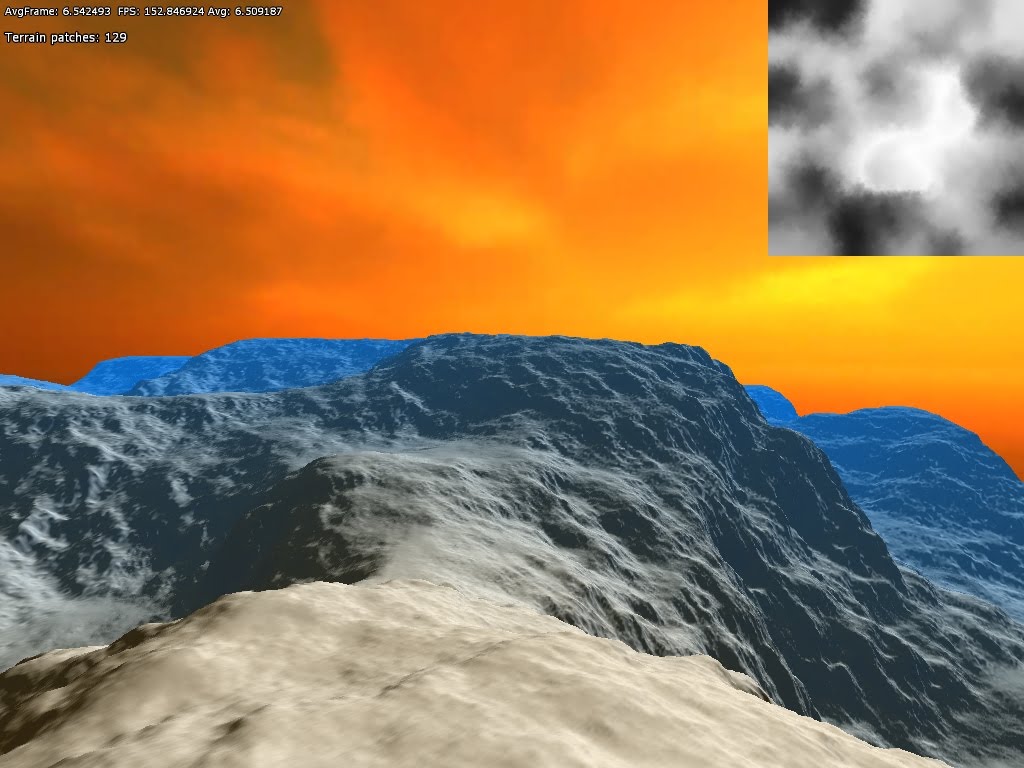
The sky texture is not very fitting. But I think this shows that the algorithm worked quite well. Also note that I did no tweaking of the LOD-level distances or patch size, so it just changes LOD level as soon as possible and probably renders more polygons because of the patch size.
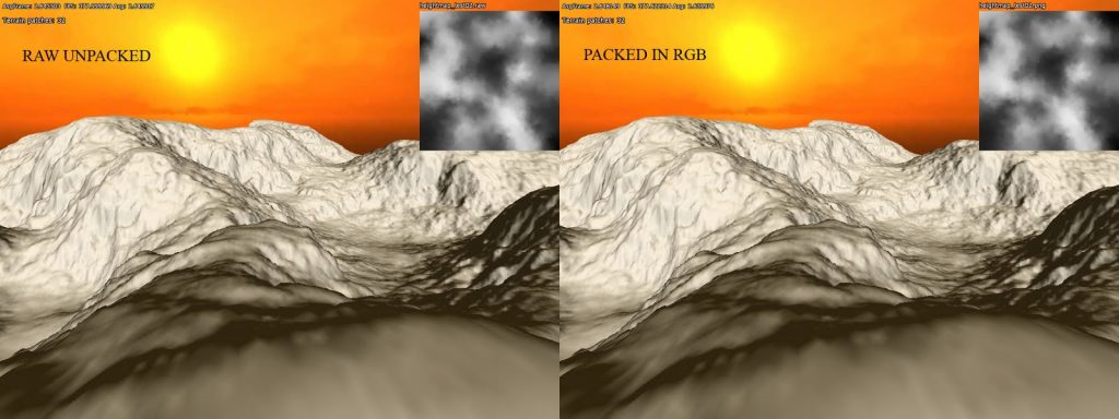
Next up I tried to pack the heightmap a bit since I did not want it to take up too much disk space. Instead of writing some kind of custom algorithm, I went the easy route and packed the height data in the same manner as I do with depth in the renderer’s G-buffer. The formula for this is:
r = height*256
g = fraction(r)*256
b = fraction(g)*256
This packs the normalized height value into three bit color channels. This 24 bit data gives pretty much all the accuracy needed and for further disk compression I also saved it as png (which has non-lossy compression). It makes the heightmap data 50% smaller on disk and it looks the same in game when unpacked:
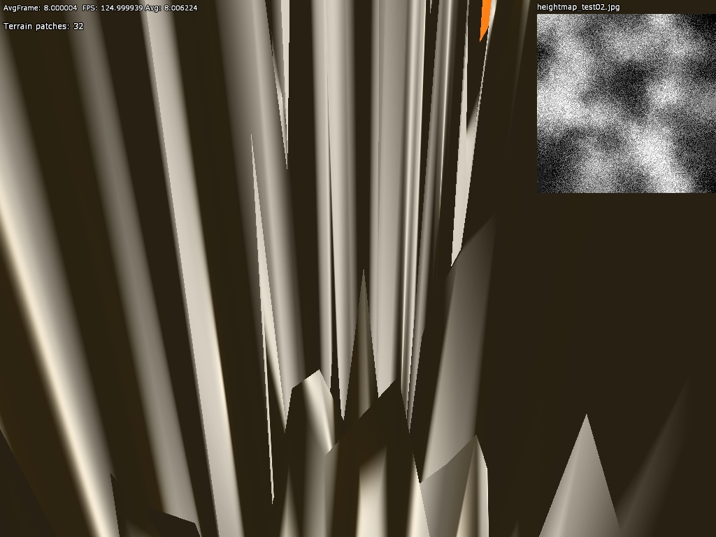
I also tried to pack it as 16 bit, only using R and B channel, which also looked fine. However when I tried saving the 24bit packed data as a jpeg (which uses lossy compresion) the result was less than nice:
Final thoughts
There is a few bits left to fix on the geometry. For example, there is some popping when changing LOD levels and this might be lessened by using a gradual change instead. I first want to see how this looks in game though before getting into that. Some pre-processing could also be used to mark patches of terrain that never need the LOD with highest detail and so on. Using hardware tesselation would also be interesting to try out and it should help add surfaces much smoother when close up.
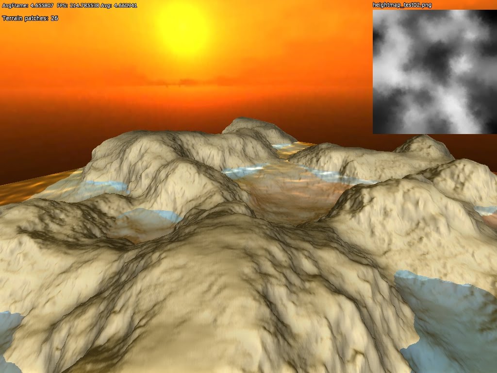
These are things I will try later on though as right now the focus is to get all the basics working. Next up will be some procedural content generation using perlin noise and that kind stuff!
And finally I will leave you with a screen container terrain, water and ssao: