Birth of a Monster Part 1: Creating Unspeakable Guidelines
Birth of a Monster Part 2: Conceptualizing the Horror
Birth of a Monster Part 3: Molding the Abomination
Birth of a Monster part 4: It’s alive!
by Olof Strand
As a modeler the first thing I noted about this character was that the concept design demanded it to be completely unique in all of its parts. Usually it is possible to mirror some parts (e.g. an arm, a leg or some cloth piece) to save texture space and maybe some production time when modeling game characters. Not so this time.
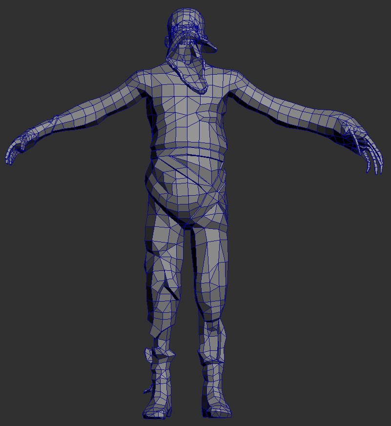
The character was based on a human body type with various deformities and modifications done to it. This meant that I could easily use a regular human base mesh as a starting point. Using already existing meshes as a starting point is, when possible, very important for production efficiency.
Another thing that needed to be taken into consideration was how the character would be rigged for animation later on. In this case the rig would be shared with another character from the game and therefore needed to be built under certain specifications (joints in specific places, etc).
When the the base modeling was done, the mesh was taken into Zbrush for a sculpting pass. The purpose of the sculpting pass is to create details that can be projected on to the final in-game mesh to make it look more detailed than it really is. Since the proportions and general shape where already defined on the base-mesh these should not be changed too much and mostly only minor details were added.
All the separate parts of the base-mesh where imported into Zbrush as separate sub-tools. This made it easy to hide, show and mask parts off. It was also possible to assign different materials to the separate parts as a visual aid. In Zbrush the mesh was subdivided several times giving me more polygons to work with. Once there was enough polygons, new details and shapes could be added by pulling, pushing and using other various tools, almost as if it was a piece of clay.
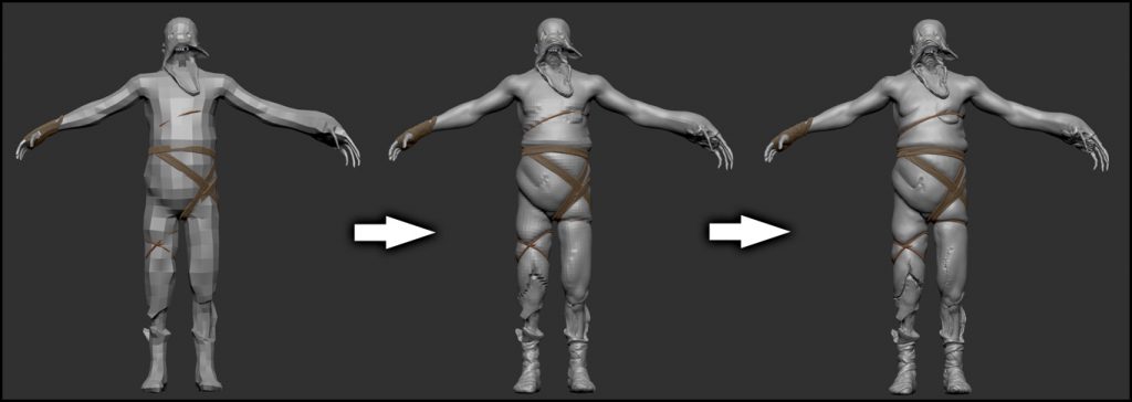
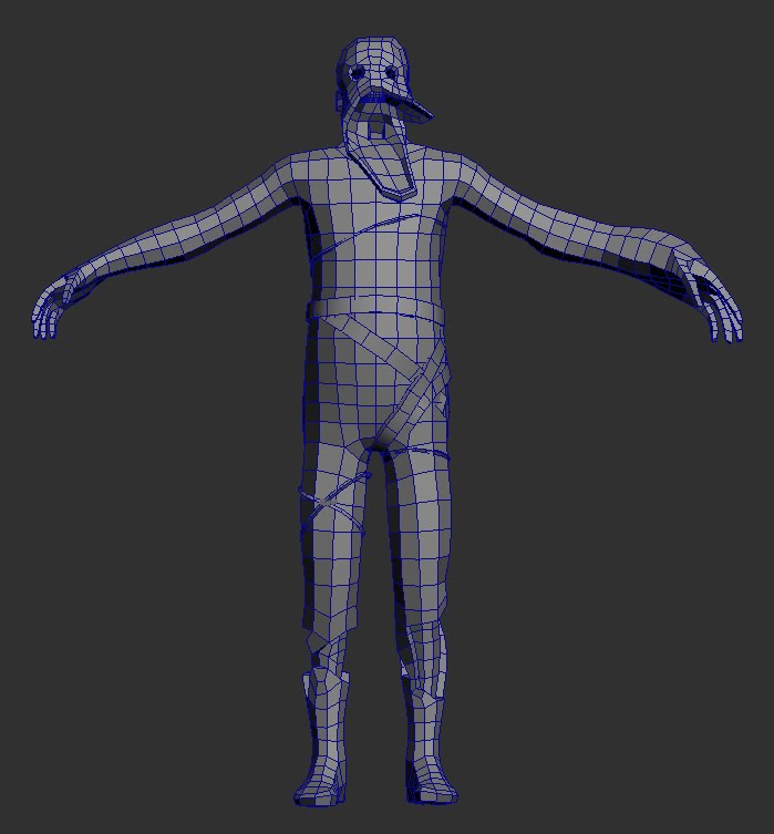
When the sculpting was done the lowest subdivision level was exported in obj-format to use as a starting point for the final low-polygon in-game mesh. The reason to make a new low polygon mesh and not use the mesh from sculpting is to optimize the number of polygons in the final mesh. This can be very important for performance when added in the game. The mesh used as a base when sculpting has a a relatively uniform tessellation (distribution and a size of polygons) and mostly a quad layout of the geometry (meaning that most polygons are four sided). The in-game mesh then had to be modified to only have geometry where it was needed. By doing this, more details could be added where really needed without decreasing any performance of the final mesh. This process is sometimes called retopologizing and can be done several different ways. Some people like to use the specialized retopologizing tools within Zbrush, but I personally like to use the regular modeling tools in my 3d software.
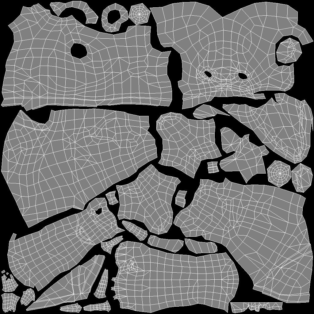
When the modeling was done it was time to create the uv-map. A uv-map is basically a way to show where parts of model belong on a flat surface, the texture. This is called a projection, and in this case a 3D to 2D one (the model is in 3D and the texture 2D). Unless the 3D object is a very simple one (like cube or plane) this is a very tricky operation and it is almost impossible to maintain the same ratios as on the model. A good example of this is to look at the various ways our planet earth (a 3D object) has turned into maps (a 2D surface) and all of the distortions and/or strange layouts that follow.
There are some conventions that should be followed when laying out this uv-map. The most important is probably to make sure to put seams (places where polygons split up during the 3d to 2d projection) in places where they are not very visible. This since it is often very hard to match up colors of pieces not next to one another on the texture. Seams can also mess up shading when using normal maps. On a humanoid character a good place to put them could be on the inside of the arms and legs for example. This character also have some irregular areas that have to be given some extra thought. For example the head had an unusual shape making the uv-mapping extra tricky. Once the placement of seams in the uv-map have been established the chunks where laid out to maximize the use of the texture space.
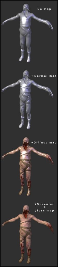
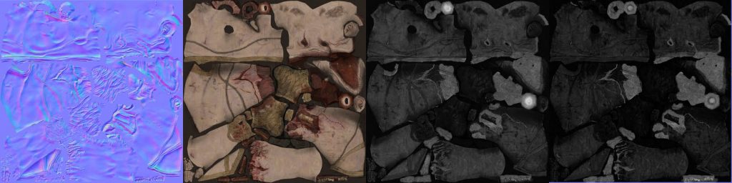
Before starting the actual texturing work I generated colors for some of the texture maps from information in the high poly mesh. The textures produced this way were the normal map and an ambient occlusion (AO) map. The normal map gives the mesh some extra detail and makes it seem like it is made up from more polygons than it really is. The AO map was to be blended into the diffuse (the base color) texture to give a greater sense of detail and form. Basically, AO is a calculation of how much light reach each point on the mesh, making creases darker and pointy details brighter.
The diffuse map represent the base color of the character and was created in Photoshop by using a mix of various photos, custom Photoshop brushes and the previously mentioned AO map. The diffuse map was extra important as it was also used as a base for creating some other maps like the specular and gloss map. These two are black and white maps that control how light will affect the model. Specular determines the strength of shininess on an areas and gloss how sharp the shininess is. Some of the detail in the diffuse was also used to add extra details in the normal map, like wrinkles and scars.
Once the texture was completed, the model was ready to be used in-game!